
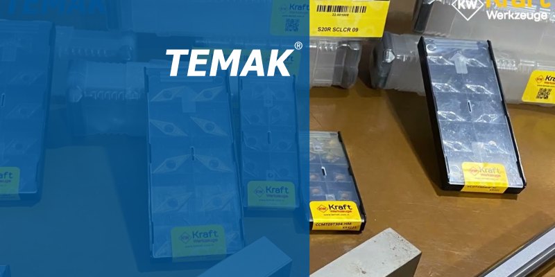
In machining operations (particularly turning and milling), selecting the right cutting tool and toolholder is vital for the tolerances achieved and for tool life. Letter and number combinations defined by ISO standards describe the geometric and technical characteristics of indexable carbide inserts and toolholders.
Watch Temak Teknik’s informative video below explaining the coding system for carbide inserts and toolholders:
1. ISO Coding of Indexable Carbide Inserts
Under the ISO standard, indexable turning and milling inserts are generally coded with standard character strings of 7 to 10 positions (e.g. C N M G 12 04 08 – PM):
- 1st Letter (Insert Geometry / Shape): Indicates the point angle and insert form.
- C: 80∘ Rhombic (external and face turning)
- D: 55∘ Rhombic / blade form (profiling and finishing)
- T: 60∘ Triangular
- S: 90∘ Square
- V: 35∘ Rhombic blade (fine profiling)
- W: 80∘ Trigon (three-sided high-strength form)
- R: Round (full radius)
- 2nd Letter (Clearance Angle): Indicates the relief (clearance) angle of the insert.
- N: 0∘ clearance angle (double-sided negative insert)
- C: 7∘ Positive insert
- P: 11∘ Positive insert
- 3rd Letter (Tolerance Class): Indicates the dimensional and corner radius tolerance of the insert (M, G, U, etc.).
- 4th Letter (Chipbreaker / Clamping Type): Denotes a design with or without a hole, or a double-sided screw-clamped design (G, M, etc.).
- 5th and 6th Digits (Cutting Edge Length): Indicate the edge length of the insert in mm (e.g. 12 = 12 mm edge length).
- 7th and 8th Digits (Insert Thickness): Indicate the thickness of the insert (e.g. 04 = 4.76 mm).
- 9th and 10th Digits (Corner Radius): Indicate the nose/corner radius of the insert (e.g. 04 = 0.4 mm, 08 = 0.8 mm, 12 = 1.2 mm).
- Suffix (Chipbreaker Geometry): Codes such as -PM, -MA, -AL define the roughing/finishing application of the insert and the type of material to be machined.
2. Coding of External Turning Toolholders
Toolholder codes indicate the shank size, cutting direction and compatible insert (e.g. P C L N R 2525 M 12):
- 1st Letter (Clamping System): Indicates how the insert is secured in the toolholder.
- P: Lever clamping
- S: Centre screw clamping (for positive inserts)
- C: Top clamp
- M: Double-action (clamp and pin) clamping
- 2nd Letter (Insert Shape): The geometry letter of the insert to be fitted in the toolholder (C, D, T, V, W, etc.).
- 3rd Letter (Toolholder Approach Angle): Represents the entering angle of the toolholder into the workpiece (L = 95∘, K = 75∘, J = 93∘, etc.).
- 4th Letter (Insert Clearance Angle): The clearance angle of the insert to be fitted (N, C, etc.).
-
5th Letter (Cutting Direction)
- R: Right-hand toolholder (cuts from right to left)
- L: Left-hand toolholder (cuts from left to right)
- N: Neutral (can cut in both directions)
- 6th and 7th Digit Groups (Shank Dimensions): Indicate the cross-section of the toolholder shank (e.g. 2525 = 25 × 25 mm shank height and width).
- 8th Letter (Toolholder Length): The overall length code of the toolholder according to ISO standards (M = 150 mm, P = 170 mm, etc.).
- Final Digits (Edge Length): Indicate the cutting edge length of the compatible insert (e.g. 12 = takes a 12 mm insert).