Temak Teknik stand at MAKTEK Eurasia 2026

MAKTEK Eurasia 2026 Fair Wrapped Up!

Held at the Tüyap Fair and Congress Centre, MAKTEK Eurasia once again took the pulse of the metalworking industry. As the Temak Teknik family, we took our place at this key industry event and shared our innovative approach and dynamic energy with the sector.

Temak Teknik stand at MAKTEK Eurasia 2026

We presented our leading cutting tool, tool holding and measuring instrument solutions from our wide product range to domestic and international visitors to our stand. Exchanging ideas face to face with our industry partners and presenting the latest options in our portfolio directly proved highly productive.

It was a great pleasure both to strengthen our ties with our long-standing business partners and to introduce Temak Teknik standards to the new customers we gained through the fair.

We would like to thank all our visitors who brought our stand to life with their strong turnout and helped us achieve this success together.

What Are Weldon Tool Holders? Features and Applications

What Are Weldon Tool Holders? Features and Applications

Weldon tool holders are rigid clamping systems widely used on CNC machining centres for roughing and heavy drilling operations that demand high metal removal rates.

Watch Temak Teknik’s video below on the design, advantages and on-machine application of Weldon tool holders:

Key Features and Advantages

  1. Prevents Axial Slippage (Pull-In): In Weldon holders, the clamping screw (set screw) seats directly on the flat on the cutting tool shank (Weldon shank / D-shank) [00:14]. This mechanical lock completely prevents the tool from slipping into or pulling out of the holder under high axial loads [00:59].
  2. Power for Heavy Cuts and Roughing: Delivers high torque transmission in heavy drilling with U-drills (indexable insert drills) and in rough end milling [00:50].
  3. Mechanical Security: Compared with collet chucks, it provides a positive lock on the shank flat in addition to friction, so the tool does not spin under high cutting forces [00:50].

Selection and Application Considerations

  • Weldon Shank Compatibility: Use only with cutting tools that have a Weldon flat on the shank [00:14]. With plain/cylindrical shank tools, the screw applies point pressure, causing runout and unstable tool behaviour [02:06].
  • Diameter Standards: Unlike collet chucks, they do not cover a wide clamping range; a separate Weldon holder of exact size is required for each shank diameter (e.g. 6, 8, 10, 12, 16, 20 mm) [00:31].
  • Runout Factor: Because the screw presses the tool from one side, they do not offer runout as low as hydraulic or shrink-fit chucks in precision finishing; their main purpose is roughing and rigidity.
Shell Mill Arbors (Face Mill Holders): Features and Selection Guide

Shell Mill Arbors (Face Mill Holders): Features and Selection Guide

In machining operations, particularly face milling and large-area machining, the equipment that clamps face mills and keyed cutting tools rigidly and precisely to the machine is known as Shell Mill Arbors (Face Mill Holders).

Watch Temak Teknik’s product information and assembly video at the link below:

Key Features and Benefits

  1. Rigidity and High Precision: With ground taper and pilot sections, the cutting tool seats on the machine rigidly and with virtually zero runout. This makes it easy to achieve the required tolerances and a high surface finish in face milling [01:50].
  2. Through-Coolant Support: A coolant channel runs through the centre of the arbor. By delivering coolant directly to the cutting edge, it improves chip evacuation and extends insert life [02:37].
  3. Versatile Use (Modularity): They are used not only for conventional face mills but also for clamping other keyed cutters such as angular milling cutters, slitting saws and gear hobs [01:31], [03:47].
  4. Range of Lengths and Tapers: In addition to CNC machining centre tapers such as BT30, BT40, BT50 and HSK-63, versions are available for universal milling machines and lathe driven tools [00:13]. Short, medium and long versions are available [03:04].

Points to Consider in Use and Length Selection

  • Choosing the Right Length: In face milling operations, always choose the shortest possible arbor to prevent deflection and vibration (chatter) [03:13]. Long arbors should only be used where deep cavities must be reached [03:22].
  • Assembly: After the drive keys are seated in their slots, the face mill is mounted on the pilot and the central locking screw is fully tightened to torque using an Allen key [04:38].
Hydraulic chuck - TEMAK

What Are Hydraulic Chucks? Features, Working Principle and Advantages

Hydraulic chucks are among the most advanced tool holding systems for CNC machining centres, designed for operations that demand high spindle speeds, maximum runout accuracy and superior surface finish.

Watch Temak Teknik’s video below on the design, working principle and application benefits of hydraulic chucks:

Key Features and Technical Advantages

  1. Outstanding Runout Accuracy: Delivers an exceptionally tight runout tolerance of 0.003 mm (3 µm), measured at 4×D from the tool tip [00:59].
  2. Hydraulic Clamping with Minimal Effort: Internal oil chambers and a single actuating screw generate maximum clamping torque with just one hex key and minimal operator effort [02:43], [03:25].
  3. Superior Vibration Damping: The hydraulic fluid inside the body absorbs micro-vibrations generated during cutting, significantly extending tool life and producing a smoother surface finish on the workpiece [01:26].
  4. Precision Reduction Sleeves: Used with dedicated precision-ground reduction sleeves. The sleeves are fully integrated at the rear and front, transmitting hydraulic pressure directly to the cutting tool shank [00:24].
  5. Corrosion Resistance and Stable Operation: Special surface coating and precision grinding make the chuck resistant to rust and corrosion, and ensure stable operation at high RPM without additional balancing [00:41].

Applications and Maintenance Requirements

  • Applications: Preferred for high-precision work that pushes machine performance to its limits in the aerospace, defence, medical, precision mould & die and automotive industries [01:54].
  • Periodic Maintenance: To prevent the hydraulic oil from losing viscosity and performance over time, hydraulic servicing should be carried out by an authorised service centre after specified operating intervals [01:08].
Asimeto Portable Digital Hardness Tester (Leeb Hardness Tester)

Asimeto Portable Digital Hardness Tester (Leeb Hardness Tester)

In machining, mould making and quality control processes, the Asimeto Portable Digital Hardness Tester is used to measure material hardness quickly and practically on site or directly at the machine.

You can access the product presentation video prepared by Temak Teknik via the link below:

Key Features and Application Benefits

  1. Rebound (Leeb / HL) Measuring Principle: The tester determines the hardness of the material by measuring the rebound velocity of an impact body after it strikes the surface of the test piece. This allows large and heavy workpieces to be checked in place without having to be transported to a laboratory.
  2. Multiple Hardness Scales: The measured Leeb (HL) value can be instantly converted on the digital display into other standard hardness units:
    • HRC / HRB (Rockwell)
    • HB (Brinell)
    • HV (Vickers)
    • HS (Shore)
  3. Ergonomic and Portable Design: Thanks to the digital display unit and the cabled impact probe, measurements can easily be taken in confined spaces and in vertical, horizontal or overhead orientations.
  4. Wide Range of Materials: Suitable for hardness testing of a variety of metals, including steel, cast iron, aluminium alloys, brass and copper.

Points to Consider When Measuring

  • Surface Preparation: For a precise and accurate result, the surface of the test piece must be clean, free of oil and smooth (sanded/ground).
  • Stability: During measurement, the probe must be held perpendicular to the workpiece, and the workpiece must not flex or vibrate. When testing lightweight parts, it is recommended to fix the part to a solid, heavy base.
Circular Saw Blades: Features, Tooth Forms and a Guide to Correct Use

Circular Saw Blades: Features, Tooth Forms and a Guide to Correct Use

Circular saw blades are cutting tools that rotate about their own axis and cut quickly and efficiently by means of teeth arranged at equal intervals around a circular disc. Used across a wide range of machines, from milling machines to dedicated circular sawing machines, circular saw blades deliver high productivity and precise cut quality when the correct blade diameter, thickness, bore diameter and tooth form are selected.

Watch Temak Teknik’s informative video below covering circular saw blades, tooth forms, material grades and cutting parameters:

Key Selection Criteria for Circular Saw Blades

1. Circular Saw Blade Diameter and Thickness

  • Diameter: Determined by the capacity of the machine being used and the depth of the workpiece to be cut. As blade diameter increases, peripheral speed rises; however, the risk of wobble also increases, so attention must be paid to clamping rigidity.
  • Thickness: Standard thicknesses in the industry generally range from 0.2 mm to 6 mm.
  • Step-Over Formula (0.75 × Thickness): When a slot wider than the blade thickness is to be cut (for example, cutting a 10 mm slot with a 4 mm thick blade), the blade thickness is not added directly when stepping over pass by pass. To avoid leaving steps or burrs on the surface, the step-over is calculated using the formula 0.75 × Blade Thickness (e.g. a step-over of 4 mm × 0.75 = 3 mm).

2. Number of Teeth and Tooth Angle Type

  • Number of Teeth

    • Coarse Pitch: Facilitates chip evacuation in soft materials (wood, aluminium) and is preferred for rough, fast cutting.
    • Fine Pitch: Gives a smoother result in hard steels and in finishing operations where a fine surface finish is required.
  • Tooth Angles

    • Wide Angle: Ideal for soft materials and wood cutting.
    • Right Angle: Used for polyamide, plastics and confectionery-type materials.
    • Narrow Angle: Suitable for hard metals (steel, aluminium, etc.) and applications requiring a high surface finish.

3. Bore Diameter and Arbor Mounting

The bore diameter (e.g. 22 mm, 32 mm, etc.) is determined in proportion to the blade diameter and thickness. To prevent runout and wobble on circular saw blades, the arbor holders should be checked axially with a dial indicator, and runout-free, rigid clamping must be ensured.

Material and Coating Options

  • HSS (High-Speed Steel) Circular Saw Blades: Widely used in general metal cutting operations. Hard coatings such as TiN (Titanium Nitride) or TiAlN (Titanium Aluminium Nitride) can be applied to increase tool life and performance.
  • Carbide-Tipped (Tungsten Carbide) Circular Saw Blades: Preferred especially for bundle/tube cutting and on high-speed CNC circular sawing machines. Their high heat resistance allows operation at higher speeds and feed rates.

Correct Use and Cooling Recommendations

  • Cutting Speed and RPM: The spindle speed (RPM) should be selected taking into account the hardness and rigidity of the workpiece. High speeds and excessive feed should be avoided on hard materials.
  • Use of Coolant: To prevent excessive frictional heat and tooth dulling, soluble oil/coolant or suitable air/oil mist systems should be applied continuously to the cutting zone.
ER Collets and Collet Chucks: Application Standards

ER Collets and Collet Chucks: Application Standards

As the most common and versatile tool clamping solution in machining operations, ER collets and ER collet chucks are designed to securely clamp a very wide range of tool shank diameters.

Watch Temak Teknik’s video below on the selection principles, advantages and correct assembly steps of ER collet systems:

Key Features and Advantages

  1. Wide Range of Size Standards: ER collet systems come in different size codes such as ER08, ER11, ER16, ER20, ER25, ER32 and ER40 [00:17]. Slim-body models (ER08, ER11) are preferred for reaching into narrow, deep cavities, while larger-body models (ER32, ER40) are chosen for roughing operations requiring high torque [01:37], [01:55].
  2. Intermediate Sizes and Flexible Clamping: In addition to standard drill or milling cutter diameters, tools with special intermediate decimal diameters such as 11.5 mm can be clamped securely thanks to the collets’ collapse range (0.5 mm, 1 mm or 2 mm clamping range) [00:26].
  3. Different Body Lengths: Holder bodies are available in 75 mm, 100 mm or longer L-length options to suit different plunge depths [01:45].

Correct Use and Limitations

  • Risks in Heavy Milling: ER collet chucks are highly economical and ideal for general milling, drilling and reaming operations [00:51]. However, in heavy rough milling the cutting load creates a risk of tool pull-out and damage to the collet slots, so Weldon, roller-type or hydraulic chucks should be preferred for such heavy operations [01:18].
  • Tapping Limitation: Standard ER collets do not provide a positive lock when clamping a tap shank, so the tap may slip under high torque. Tapping chucks with a safety clutch or spring-loaded tap holders should be used for tapping operations [01:00].
  • Assembly Sequence: During assembly, the collet should first be seated at an angle into the eccentric ring inside the nut, and only after hearing a “click” should the nut be screwed onto the holder body [02:04].
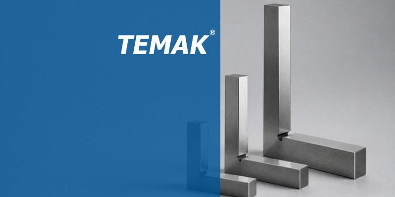
The Key to Precision Measurement: Types of Squares and Their Applications

The Key to Precision Measurement: Types of Squares and Their Applications

In machining, assembly and quality control, verifying the flatness of a part’s surface or the squareness between surfaces is one of the most critical steps. To carry out these checks quickly and reliably, different types of squares designed for specific measuring requirements are used.

In this article, with guidance from Temak Teknik, we look at the types of squares most commonly used in manufacturing and workshop environments, their functions and how to store them correctly.

1. Knife-Edge Squares (Light-Gap Inspection Squares)

Knife-edge squares are high-precision measuring instruments used to check the flatness and 90-degree squareness of precision surfaces using the light-gap method.

  • Design: The edges are specially ground on both sides to form a fine, knife-like bevelled edge.
  • Use: The square is placed on the surface to be checked and viewed against the light. Even the smallest surface irregularity or angular deviation is detected instantly by the light passing under the knife edge.
  • Sizes: Available in various lengths such as 100 mm, 150 mm, 200 mm and 250 mm.

2. Try Squares (Squares with Stock)

Thanks to the stock (shoulder) at the base, try squares make squareness checks and part alignment considerably easier.

  • Practical Use: By resting the stock against the reference part, 90-degree squareness can be checked quickly by hand.
  • Workshop Application: When mounting a vice on a CNC machining centre, vice alignment can be achieved in seconds by using a try square against the T-slots or reference surfaces. This significantly reduces the time spent on setting up with a dial indicator.

3. Fixed-Angle Squares

These are squares fixed by design at specific standard angles.

  • Features: They are typically produced at angles that are multiples of 30 and 45 degrees, such as 45°, 60°, 120°, 135° and 150°.
  • Applications: They are used as reference gauges on production lines where joints or chamfers at specific standard angles are checked.

4. Universal Squares and Protractors

These are flexible instruments capable of measuring angles to degree-and-minute accuracy.

  • Vernier and Optical Bevel Protractors: They feature a vernier scale for degree/minute readings and magnifying lenses that make angle reading easier. They can be set and locked at the required angle.
  • Simple and Hinged Protractors: These models work on the principle of a protractor to check angles up to 180 degrees. They are widely used for copying and verifying angles in steel construction, metal fabrication and furniture manufacturing.

5. Correct Use and Care of Squares

Squares are precision inspection instruments, ground and toleranced to international standards. To extend their life and preserve their accuracy in workshop conditions, the following points should be observed:

  1. Do Not Leave Them Loose on the Machine: Avoid placing squares on top of spanners, hammers, workpieces or chip deposits.
  2. Store Them in Their Case: When not in use, keep them in their original wooden case with foam lining to protect them from moisture and impact.
  3. Keep Them Clean: After use, remove any chips and oil residue and protect them against corrosion with a thin protective film of oil.
HSS Milling Cutters: Types, Features and Applications in Machining

HSS Milling Cutters: Types, Features and Applications in Machining

Widely used in machining operations, HSS (High Speed Steel) end mills are cutting tools that stand out for their high toughness, impact resistance and economical cost. With a more flexible structure than carbide tools, HSS milling cutters can be used reliably, especially in interrupted cuts and in standard-tolerance manufacturing processes.

Watch Temak Teknik’s informative video below covering HSS end mill types, flute counts, coating options and the benefits of regrinding:

Advantages and Key Features of HSS Milling Cutters

  1. High Impact Resistance and Toughness: Far less brittle than carbide end mills. They work reliably without tool breakage on machines with low rigidity and in interrupted or vibration-prone cutting operations.
  2. Low Cost and Easy Regrinding: Purchase costs are low. In addition, end and flank regrinding can be carried out easily and very economically on universal or compact end mill grinding machines.
  3. Versatility in Workpiece Materials: Ideal for machining mild steels ( < 180 HB), aluminium, copper, wood, plastics and composite materials.

Material Composition and Coating Options

  • HSS-Co (Cobalt HSS): Contains between 5% and 8% cobalt. The cobalt content increases the tool’s resistance to high temperatures and extends its cutting life.
  • Uncoated HSS Milling Cutters: Preferred uncoated and with extremely sharp cutting edges, especially when machining aluminium, copper and stainless materials, to prevent material from adhering to the tool (built-up edge).
  • Coated HSS Milling Cutters (e.g. Zirconium): Where high surface quality is required, special coatings are applied that reduce friction and delay wear.

HSS Milling Cutter Types by Flute Count and Form

  • Single-Flute Cutters: Used for cutting wood, acrylic, plastics and composite materials (on router machines) to evacuate chips rapidly.
  • 2- and 3-Flute Cutters: Preferred for machining aluminium and soft metals, and for keyway cutting (plunge milling) operations.
  • 4-Flute Cutters: Commonly used in general steel machining and side milling operations.
  • 6-Flute and Roughing (Serrated) Cutters: Either break chips into small segments to allow high metal removal rates (roughing), or deliver a precise surface finish thanks to their multi-flute design.
  • Form Cutters: Special profile types are available, including square (90° corner), ball nose (corner radius), tapered and special chamfering forms.
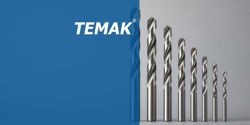
What Are HSS Drills? Helix Angles, Types and Applications

What Are HSS Drills? Helix Angles, Types and Applications

Around 33% of the work carried out in machining processes consists of drilling operations. In such a frequently repeated operation, choosing the right drill bit extends tool life, improves surface finish and lowers manufacturing costs. One of the indispensable tools of any workshop, HSS (High-Speed Steel) drills are among the most widely used drilling tools thanks to their ability to be reused after regrinding.

In this article, guided by Temak Teknik, we examine the types of HSS drills, their helix angles, the importance of cobalt content and coating technologies.

1. Point and Helix Angles by Material (Types N, H, W)

The point angles and helix (flute) angles of drills vary according to the hardness, chip formation and brittleness of the material to be machined:

  • Type N (Standard Drills)

    • Point Angle: Usually around 118°.
    • Helix Angle: Between 18° and 30°.
    • Generally preferred for drilling general-purpose steels and standard materials. For hard and brittle materials, the point angle can be increased to 135° – 140° to enlarge the contact surface.
  • Type H Drills

    • Helix Angle: Features a lower helix angle of around 10° – 15°.
    • Offers greater resistance when drilling hard, hardened or brittle materials.
  • Type W Drills

    • Helix Angle: Features a steeper helix angle of between 35° and 40°.
    • Used to evacuate chips quickly in soft materials such as aluminium, brass and plastics, or in materials where chips must be cleared easily.

2. Advantages of HSS-Co (Cobalt) Drills

Standard HSS drills dull quickly in materials that generate high heat during machining and tend to work-harden, such as stainless steels in particular.

  • Cobalt Content: HSS-Co drills contain between 6% and 8% cobalt (Co) alloy.
  • Heat and Wear Resistance: The cobalt content increases the drill’s strength at high temperatures and improves its wear resistance.
  • Application: In stainless steels, heat-resistant steels and difficult alloys, using HSS-Co significantly extends tool life.

3. Coated HSS Drills and Performance

Special surface coating technologies (for example zirconium coating) are used to improve the performance of HSS drills:

  • Reduced Friction: The coating minimises friction at the cutting interface between the drill and the material.
  • Surface Finish: Ensures a smooth finish on the inner surface of the hole.
  • Longer Tool Life: Because it prevents heat build-up and delays wear, it allows more and deeper holes to be drilled in a single run.

In summary: Rather than using the same drill for every material in machining processes, selecting an HSS drill with the helix angle and coating suited to the material type, hardness and operating conditions will increase your manufacturing efficiency.