Precision Parallel Sets: Features, Applications and Accurate Set-Up

Precision Parallel Sets: Features, Applications and Accurate Set-Up

In machining operations (especially on CNC machining centres and universal milling machines), the calibrated accessories that ensure a workpiece is level, horizontally parallel and raised to the required machining height when clamped in a vice or on the machine table are called parallel sets.

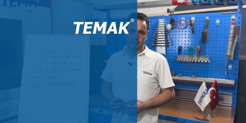
Watch Temak Teknik’s video below explaining the types of parallels, their precision tolerances and the correct way to use them on the machine:

Construction and Technical Specifications of Parallels

  1. High Precision and Surface Quality: The precision ground parallels are square to 90°, with a height and parallelism tolerance between pairs of 0.01 mm (one hundredth of a millimetre) [00:49].
  2. High Hardness: They are made from heat-treated tool steel and have a hardness of approximately 60 HRC [01:30].
  3. Standard Sizes

    • Lengths: Generally available in standard lengths of 100 mm, 125 mm and 150 mm [00:58].
    • Width / Thickness: The most widely used in industry are 5 mm (thin parallels) and 10 mm (thick parallels) wide [01:20].
    • Height Increments: Sets contain matched pairs in a range of heights such as 14, 16, 18, 20, 22, 24, 26, 28, 32, 35, 40, 45 and 50 mm [03:00].

Applications and Building Combinations

  • Raising the Workpiece and Ensuring Parallelism: Placed between the vice jaws, they allow the workpiece to be clamped parallel to the base and at the required machining height [02:50].
  • Combinations (Stacked / Side-by-Side Use): When an intermediate size other than the standard heights is required (e.g. 55 mm), the precise height can be achieved by stacking 5 mm or 10 mm thick parallels [03:14].
  • Machine and Gauge Calibration: Used as support elements for precise levelling of machine tables, fixtures or gauges [00:35].

Points to Consider When Using Parallels on the Machine

  • The Worst-Case Scenario: Cutting or Drilling into the Parallels: In drilling or slotting operations on the workpiece, if the drill/cutter length is not set correctly, both the parallels and the cutting tools will be damaged [02:20]. The clearance under the workpiece (the distance between the parallels) must always be wider than the drill/tool diameter [01:52].
  • Chip Cleaning: At every part change, the surfaces of the parallels and the vice base should be cleaned with compressed air. Even a single small chip trapped under a parallel or on the contact surface with the part will compromise the part’s 0.01 mm parallelism accuracy [03:52].
  • Seating with a Plastic / Copper Mallet: After the workpiece has been clamped in the vice, it is tapped lightly from above with a plastic or copper mallet to ensure it is fully seated on the parallels [04:45].
  • Checking for Movement (Play): Once clamping is complete, check by pulling gently on the parallels by hand. If one of the parallels moves, the part is seated at an angle/skewed in the vice [05:14].
Types of Collet Chucks (ER Collet Chucks) and Their Features

Types of Collet Chucks (ER Collet Chucks) and Their Features

In the world of machining, Collet Chucks (ER Collet Chucks) are the most widely used and economical tool holding systems for a broad range of operations such as drilling, milling, boring and reaming.

Watch Temak Teknik’s product information video at the link below:

Key Features and Advantages

  1. High Clamping Force and Full-Circumference Grip: As the nut is tightened, the slotted structure of the collets grips the tool shank uniformly through 360 degrees, providing a strong hold [00:19].
  2. Wide Product and Diameter Range: ER collet systems range from ER08 through ER11, ER16, ER20, ER25, ER32, ER40 and ER50 [01:05]. As a result, all cutting tools with shank diameters from 0.5 mm to 34 mm can be clamped in a single holder body simply by changing collets [02:14].
  3. Flexibility with Intermediate/Decimal Diameters: Whereas Weldon or hydraulic chucks can only hold standard whole diameters (e.g. 8 mm, 10 mm), ER collets make it easy to clamp tools with special/decimal shank diameters such as 10.1 mm or 10.5 mm [01:46].
  4. Economical and Modular: By purchasing a single collet chuck body and changing the collet set inside it, dozens of drills, end mills and reamers of different diameters can be clamped [00:35].

Tolerances to Consider When Selecting Collets

  • Standard vs. Precision Collets: Type A (standard) and Type B (precision) collets are available on the market. Their accuracy generally ranges from 0.015 mm to 0.003 mm (3 microns) [01:21].
  • Single-Size vs. Clamping-Range Collets: Collets marked with a single size (e.g. just 10) are dedicated to that diameter only and have much lower runout values. Collets marked with a range (e.g. 10-11) offer 1 mm of collapse range, but their runout accuracy is slightly lower than that of single-size collets [01:30].
Workpiece Zeroing on CNC Machining Centres: Edge Finders and Their Types

Workpiece Zeroing on CNC Machining Centres: Edge Finders and Their Types

In CNC and machining operations, accurately determining the position of the workpiece on the machine is the most fundamental step for precision machining. Workpiece zeroing probes (edge finders), used for axis zeroing, allow workpiece reference points on the X and Y axes to be defined conveniently and with high accuracy.

Watch Temak Teknik’s informative video below covering probe types and application steps:

Types and Features of Edge Finders

Different probe solutions are used depending on shop-floor needs and machine infrastructure:

1. Mechanical Edge Finders

Mechanical edge finders consist of a two-stage cylindrical body combined with a spring mechanism. They are divided into three groups according to their material:

  • Steel Edge Finders: Offer an economical solution. However, they may become magnetised over time due to friction.
  • Stainless Steel Edge Finders: Eliminate the risk of magnetisation, providing more stable measurement.
  • Ceramic Edge Finders: Extremely high wear resistance. Their shock-resistant, non-magnetic design ensures a long service life.

2. Light and Sound Edge Finders

On conductive workpieces, these systems complete an electrical circuit on contact and give both a visual (LED) and an audible (buzzer) signal:

  • No Spindle Rotation Required: Measurement is made by direct contact without rotating the spindle (while stationary).
  • High Precision: Provides accuracy at the 0.005 mm (5 micron) level.
  • Note: For light/sound edge finders to work, the workpiece and machine table must be conductive (mechanical edge finders should be preferred for plastic or insulated materials).

How to Zero Correctly with a Mechanical Edge Finder

To zero a part to 0.01 mm (1%) accuracy with a mechanical edge finder, follow these steps:

  1. Speed Setting: Mechanical edge finders are used with the spindle rotating. The recommended speed range is 400 – 600 rpm (ideally 500 rpm). Higher speeds can cause the spring mechanism to fly apart and damage the equipment.
  2. Gradual Approach: Approach the workpiece using the handwheel. At first contact, the lower tip of the probe rotates eccentrically (wobbling).
  3. Kick-Off Point (Reference Moment): As contact continues, the axial wobble disappears and, at the moment it is exactly on axis, the lower tip makes a sideways “kick-off” movement. Stop the axis movement as soon as this kick is observed.
  4. Defining the Coordinate: Taking the position at the moment of kick-off as reference, the radius of the probe tip used (e.g. 5 mm for a Ø10 mm tip) is added to or subtracted from the axis value.

Critical Points to Observe in Use

  • Do Not Use on the Z Axis: Edge finders are designed only for horizontal contact on the X and Y axes. Applying vertical pressure on the Z axis will break the probe and damage the machine.
  • Observe the Speed Limit: The speed limits specified by the manufacturer for mechanical edge finders must not be exceeded.
  • Magnetisation Check: To prevent measurement errors, it is recommended to demagnetise steel edge finders periodically or to choose ceramic/stainless models.

For edge finder types and technical details that provide fast and precise zeroing of your workpieces, visit our website temak.com.tr and get support from our expert team.

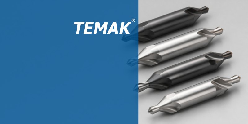
What Is a Centre Drill? Applications, Angles and Selection Criteria

What Is a Centre Drill? Applications, Angles and Selection Criteria

In machining — whether on CNC machining centres or on manual/CNC lathes — locating the hole centre before drilling is of great importance. Starting directly with a standard drill can cause the drill point to walk on the surface, the hole to drift off axis or even the tool to break.

In this article, with guidance from Temak Teknik, we look at the main functions, types, angle standards and rules for correct use of centre drills.

1. Main Purpose and Features of a Centre Drill

The main task of a centre drill is centring and guiding:

  • Prevents Axial Drift: Prevents the drill point from walking, especially on curved, contoured or angled surfaces.
  • Rigid Design: Centre drills are made from tool steel and do not deflect. Under axial stress or misalignment they break rather than bend. This ensures that the initial centring is made perfectly square.
  • Countersink Depth: Unless there is a specific technical requirement, a centre drill is used by plunging it to approximately half the length of its countersink section.

2. Centre Drill Types and Material Grades

Centre drills are made from different materials depending on the hardness of the workpiece material, the machine type and the operating conditions:

  • HSS-Co (8% Cobalt): One of the new-generation tool steels. Its high cobalt content makes it wear-resistant and delivers long tool life.
  • Carbide Centre Drills: Used in very hard materials and for work requiring high precision. However, as carbide is a brittle material, it must be used in vibration-free conditions; on machines prone to vibration it can break quickly.
  • Long Centre Drills: Preferred on machining centres (VMC) or for centring holes in deep or hard-to-reach areas.

3. Standards and Angle Values

Centre drills are manufactured to specific industry standards:

  • Standards and Angles: The most common centre drills on the market conform to DIN 333 and generally have a 60° angle. Depending on CNC applications and requirements, this angle can go up to 90°.
  • Pilot and Shank Diameter Relationship: Centre drills are designated by their pilot diameter (for example, a centre drill with a 2 mm pilot diameter may have a 5 mm shank/body diameter).
  • Choosing the Right Diameter: A centre drill matching the diameter of the drill to be used should be selected. Using an oversized centre drill creates an excessively wide centre countersink in the workpiece and impairs dimensional accuracy.

4. Rules to Observe in Use

  1. Facing: On a lathe, the face of the workpiece must always be faced to obtain a flat surface before drilling the centre hole.
  2. Short Clamping: Rigidity should be increased by clamping the part and the centre drill holder (drill chuck or collet) as short as possible.
  3. Speed and Feed Calculation: The cutting speed (Vc) should be determined according to the workpiece material (steel, cast iron, aluminium etc.), and the spindle speed calculated accordingly ($n = \frac{V_{c} \times 1000}{\pi \times d}$).
  4. Centre Hole Depth Standards: In series production or when supporting parts with a tailstock centre, standard centre hole depth tables proportional to the material diameter should be used as a reference.
Deburring Tools: Types, Deburring Methods and Applications

Deburring Tools: Types, Deburring Methods and Applications

In machining operations (turning, milling, drilling, etc.), sharp burrs (burr residues) form on part edges, at hole entrances or on internal surfaces after cutting. Hand tools known as deburring tools (deburring scrapers) are used to remove these burrs, give the part a clean chamfer/radius and ensure operator safety.

Watch Temak Teknik’s detailed review video below showing deburring tools, blade angles, special blade forms and application methods:

Deburring Blade Types and Angle Classification

  • 10° Blades (e.g. C10 / B10): Used for general deburring of standard steels and soft metals [01:57].
  • 20° Blades (e.g. C20 / B20): Offer a steeper cutting angle; suitable for deeper chamfering at hole entrances and along side edges [02:08].
  • TiN (Titanium Nitride) Coated Blades: Provide long tool life on hardened steels, heat-treated parts and highly abrasive hard materials [02:17].
  • C-Form (Hook / Notch) Blades: Used to remove hard-to-reach burrs on the back face of holes by inserting the blade through the hole and pulling it back [05:00].
  • Ceramic Blade Deburring Tools: Enable micro-deburring and finishing of materials such as plastics, polyamide and acrylic without scratching the part [10:50].

Application Methods and Deburring Tool Types

1. Deburring Holes and Outside Diameters (Swivel Ball-Bearing Handles)

Thanks to the ball bearing at the tip of the handle, the blade can rotate freely through 360°. By turning the tool around the hole or along the edge of a shaft, the operator produces a smooth, circular chamfer [03:00].

2. Back-Side Hole Deburring (Telescopic / Hook Holders)

For burrs left on the back face of the part, the hook blade is inserted into the hole, seated against the back face and pulled back to shear off the burr [07:41].

3. Deburring 90° Corners and Side Faces

Double-sided curved or angled blades sit precisely on 90∘ corners. A corner chamfer is produced with a single, continuous pulling stroke [06:59].

4. Micro-Finishing and Precision Operations

In the defence, aerospace and electronic enclosure industries, extremely fine, scalpel-shaped micro-deburring tools used under a microscope are preferred for removing micro-burrs [11:29].

Points to Consider During Use

  • Correct Amount of Pressure: Pressing too hard at the hole entrance or along edges restricts the blade’s movement. Apply gentle pressure, letting the free-rotating ball bearing do the work [01:09].
  • Continuous Stroke: Do not pause while drawing the tool along side faces; otherwise a dwell mark will be left on the workpiece surface [03:45].
  • Convenient Storage: By opening the rear cap of ergonomic deburring handles, spare blades can be stored safely inside the body [12:12].
Roller Lock Chucks (Power Milling Chucks): Features and Applications

Roller Lock Chucks (Power Milling Chucks): Features and Applications

One of the most rigid systems preferred on CNC machining centres for high-speed operation, heavy-duty roughing and processes requiring a fine surface finish is the Roller Lock Chuck (Power Milling Chuck).

Watch Temak Teknik’s video below explaining the design, advantages and assembly of power milling chucks:

Key Features and Advantages

  1. Rigidity and High Clamping Force: Thanks to the needle roller/bearing mechanism inside, a uniform pressure is applied at multiple points when the nut is tightened. After shrink-fit chucks, it is one of the systems offering the highest clamping torque and rigidity [00:19], [01:45].
  2. Vibration Damping (Damping Effect): The roller bearing mechanism dampens the cutting loads and vibration generated during operation. This extends cutting tool life and delivers an excellent surface finish on the workpiece [00:20], [00:38].
  3. High-Speed Capability: Provides runout-free, stable operation at high RPM, ensuring precise dimensional accuracy [00:19].
  4. Quick and Easy Tool Changes: With its dedicated adjustable wrench, it can be tightened and released quickly at the machine without the need for hydraulic or shrink-fit units [02:04].
  5. Special Solid Collet Design: Power milling chuck collets have a solid, rigid body that is not slotted at the rear [01:38].

Applications and Disadvantages

  • Applications: Used in critical sectors such as aerospace, defence, automotive and mould making, where tolerances go down to one micron (0.001 mm) and a high surface finish is required [01:04].
  • Dimensional Constraints: The body and nut are thicker and heavier than those of standard collet chucks. They can therefore present a risk of contact in very narrow slots or deep side-wall machining operations [00:46].
  • Points to Note When Clamping: Excessive force should not be applied when tightening with the special ratchet/adjustable wrench; overloading can deform the wrench slots on the nut [02:56].
ISO Coding of Carbide Inserts and Turning Toolholders

ISO Coding of Carbide Inserts and Turning Toolholders

In machining operations (particularly turning and milling), selecting the right cutting tool and toolholder is vital for the tolerances achieved and for tool life. Letter and number combinations defined by ISO standards describe the geometric and technical characteristics of indexable carbide inserts and toolholders.

Watch Temak Teknik’s informative video below explaining the coding system for carbide inserts and toolholders:

1. ISO Coding of Indexable Carbide Inserts

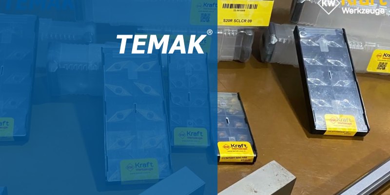
Under the ISO standard, indexable turning and milling inserts are generally coded with standard character strings of 7 to 10 positions (e.g. C N M G 12 04 08 – PM):

  • 1st Letter (Insert Geometry / Shape): Indicates the point angle and insert form.
    • C: 80∘ Rhombic (external and face turning)
    • D: 55∘ Rhombic / blade form (profiling and finishing)
    • T: 60∘ Triangular
    • S: 90∘ Square
    • V: 35∘ Rhombic blade (fine profiling)
    • W: 80∘ Trigon (three-sided high-strength form)
    • R: Round (full radius)
  • 2nd Letter (Clearance Angle): Indicates the relief (clearance) angle of the insert.
    • N: 0∘ clearance angle (double-sided negative insert)
    • C: 7∘ Positive insert
    • P: 11∘ Positive insert
  • 3rd Letter (Tolerance Class): Indicates the dimensional and corner radius tolerance of the insert (M, G, U, etc.).
  • 4th Letter (Chipbreaker / Clamping Type): Denotes a design with or without a hole, or a double-sided screw-clamped design (G, M, etc.).
  • 5th and 6th Digits (Cutting Edge Length): Indicate the edge length of the insert in mm (e.g. 12 = 12 mm edge length).
  • 7th and 8th Digits (Insert Thickness): Indicate the thickness of the insert (e.g. 04 = 4.76 mm).
  • 9th and 10th Digits (Corner Radius): Indicate the nose/corner radius of the insert (e.g. 04 = 0.4 mm, 08 = 0.8 mm, 12 = 1.2 mm).
  • Suffix (Chipbreaker Geometry): Codes such as -PM, -MA, -AL define the roughing/finishing application of the insert and the type of material to be machined.

2. Coding of External Turning Toolholders

Toolholder codes indicate the shank size, cutting direction and compatible insert (e.g. P C L N R 2525 M 12):

  • 1st Letter (Clamping System): Indicates how the insert is secured in the toolholder.
    • P: Lever clamping
    • S: Centre screw clamping (for positive inserts)
    • C: Top clamp
    • M: Double-action (clamp and pin) clamping
  • 2nd Letter (Insert Shape): The geometry letter of the insert to be fitted in the toolholder (C, D, T, V, W, etc.).
  • 3rd Letter (Toolholder Approach Angle): Represents the entering angle of the toolholder into the workpiece (L = 95∘, K = 75∘, J = 93∘, etc.).
  • 4th Letter (Insert Clearance Angle): The clearance angle of the insert to be fitted (N, C, etc.).
  • 5th Letter (Cutting Direction)

    • R: Right-hand toolholder (cuts from right to left)
    • L: Left-hand toolholder (cuts from left to right)
    • N: Neutral (can cut in both directions)
  • 6th and 7th Digit Groups (Shank Dimensions): Indicate the cross-section of the toolholder shank (e.g. 2525 = 25 × 25 mm shank height and width).
  • 8th Letter (Toolholder Length): The overall length code of the toolholder according to ISO standards (M = 150 mm, P = 170 mm, etc.).
  • Final Digits (Edge Length): Indicate the cutting edge length of the compatible insert (e.g. 12 = takes a 12 mm insert).
Carbide Inserts and Material Knowledge: ISO Material Groups and Colour Codes

Carbide Inserts and Material Knowledge: ISO Material Groups and Colour Codes

When selecting inserts for machining operations, the physical and chemical properties of the workpiece material are the deciding factor. Under international standards (ISO), inserts are classified with specific letter and colour codes according to the workpiece material groups. Choosing the wrong insert leads to rapid tool wear, breakage, built-up chips or poor surface finish on the workpiece.

Watch Temak Teknik’s information video on carbide inserts, ISO material classes and choosing the right insert below:

ISO Material Groups and Colour Codes

Indexable carbide inserts are divided into 6 main groups according to the workpiece material:

1. P Group: Steels (Blue)

  • Scope: Carbon steels, alloy steels, cast steels and non-heat-treated tool steels (1020, 1040, 1045, 4140, 2379 etc.).
  • Chip Formation: Generally produces continuous, helical chips. Cutting resistance is moderate and machinability is very good.

2. M Group: Stainless Steels (Yellow)

  • Scope: Stainless steels containing at least 12% chromium, nickel or molybdenum (e.g. 304, 316, duplex stainless steels).
  • Characteristics: Built-up edge and notch wear occur during cutting. Sharp insert geometries with high heat resistance should be selected.

3. K Group: Cast Iron (Red)

  • Scope: Grey cast iron, nodular (ductile) cast iron and malleable cast iron.
  • Chip Formation: Produces short, brittle chips (like grains of bulgur or wheat). As little chip breaking is required, the chipbreaker forms on these inserts are generally flat or plain.

4. N Group: Non-Ferrous Metals (Green)

  • Scope: Aluminium alloys, copper, brass, bronze and various plastics such as polyamide, Delrin and cast nylon.
  • Characteristics: These inserts have polished (bright) and extremely sharp geometries to reduce friction and prevent material smearing. They offer long life at high cutting speeds.

5. S Group: Heat-Resistant Superalloys and Titanium (Orange / Brown)

  • Scope: Nickel-, cobalt- or titanium-based high heat-resistant alloys (Inconel, Hastelloy, titanium etc.).
  • Characteristics: These materials are much harder to cut than stainless steels, generate high heat during machining and cause work hardening. Tool life is short, and inserts with special coatings are required.

6. H Group: Hardened Materials (Grey)

  • Scope: Heat-treated hardened steels and cast irons between 45 and 65 HRC (Rockwell).
  • Characteristics: Extremely high cutting temperatures and high strength are involved. In conditions free of impact and vibration, ceramic or CBN (Cubic Boron Nitride) inserts are also preferred alongside carbide inserts.

Key Recommendations for Choosing the Right Insert

  1. Part Form and Surface Brightness: When machining aluminium and plastics, green-coded (N class) bright polished inserts should be chosen to avoid dulling or built-up edge (BUE) [01:38].
  2. Recommendation for Plastics: For plastic-based materials such as polyamide, Delrin and cast nylon, inserts with aluminium geometry (N) provide a smooth cut and prevent the part from melting and burring [01:53].
  3. Ceramic Alternative: In hardened materials (H group), where there is no risk of impact, heat-resistant ceramic inserts or CBN inserts can increase cutting life many times over
Solid Carbide End Mills: Features, Flute Geometries and Applications

Solid Carbide End Mills: Features, Flute Geometries and Applications

Solid Carbide (Solid Cemented Carbide) End Mills are among the most widely preferred cutting tools in machining operations for achieving high precision, long tool life and high cutting speeds. Carbide rods, produced by powder metallurgy through blending and sintering tungsten carbide and cobalt powders, are ground to tight tolerances (h6 / h9) with diamond grinding wheels to form the end mill.

Watch Temak Teknik’s informative video below covering solid carbide end mill types, helix angles, coating types and flute selection by workpiece material:

Advantages of Solid Carbide End Mills

  1. High Speed and Feed Capability: Offer greater heat resistance and hardness than HSS tools. From micro-milling (0.5 mm, 1 mm) up to large diameters, high speeds of 15,000 − 20,000 rpm can be reached [03:59].
  2. High Surface Quality and Rigidity: The solid carbide construction minimises deflection and chatter, resulting in an excellent surface finish and tight dimensional tolerances [04:08].
  3. Cost Efficiency (Machine Hourly Cost): By significantly reducing cycle times, they lower the cost per part on machines used for series production [04:24].

End Mill Types by Cutting Edge Form

  • Square (90° Corner) End Mills: The most widely used type for side milling, standard slotting, pocketing and shoulder milling operations [02:49].
  • Corner Radius End Mills: Radii such as 0.5 mm, 1 mm are applied to the sharp corners of the tip to increase the edge’s resistance to breakage. They improve surface quality when stepping over on side walls [03:07].
  • Ball Nose End Mills: Used in mould making for machining contoured, curved 3D surfaces and for finishing operations [03:29].

Relationship Between Helix Angle and Surface Quality

  • 30° – 40° Helix Angle: Provides balanced cutting forces and chip evacuation for general steels and roughing/semi-finishing operations [01:42].
  • 45° – 50° High Helix Angle: Increases the tool’s engagement with the workpiece, producing smoother surfaces; preferred for finishing operations [01:50].

Flute Count and Coating Selection by Workpiece Material

  • 1- and 2-Flute End Mills: Generally preferred in a polished/sharp design for wood, plastics, polyamide, acrylic and thin-walled aluminium profiles (on router machines) to prevent chip packing [06:48].
  • 3-Flute End Mills: Ideal for machining aluminium alloys and non-ferrous metals, as they offer large chip evacuation capacity and sharpness [06:20].
  • 4-Flute End Mills: The standard choice for milling general steels, cast iron and hardened materials [06:10].
  • 6-Flute and Multi-Flute End Mills: Used in steel finishing operations where high surface quality is the goal, or in roughing operations with chip-breaker flutes [05:36].

Coating Technologies (TiAlN / TiSiN)

Special micron-level coatings used on carbide end mills, such as TiAlN (Titanium Aluminium Nitride) or TiSiN (Titanium Silicon Nitride), reduce friction, retain their hardness at high temperatures and increase tool life by 30% to 40% [05:22].

T-Slot Cutters: Types, Standards and Applications

T-Slot Cutters: Types, Standards and Applications

Frequently used in the manufacturing industry and in machining operations, T-slot cutters take their name from the cutting tooth structure at the end of, or around, a cylindrical shank that resembles the letter T. They are generally preferred for machining T-slots, circlip grooves, dovetails (slideway seats) and special radius profiles on the inner or side faces of parts.

Watch Temak Teknik’s informative video below covering T-slot cutter types, angle types, material grades and application tips:

T-Slot Cutter Types and Designs

T-slot cutters are produced in different geometries according to the form to be machined and the type of operation:

1. Straight / Standard T-Slot Cutters

Used for cutting standard T-slots on machine tables, internal side grooves and circlip grooves. The teeth can be arranged staggered (angled) or symmetrically to distribute the cutting load.

2. Dovetail (Angled) Cutters

Used for machining the angled mating seats that slide within one another in slideway systems.

  • Widely available in standard angles of 45° and 60°.
  • Small-diameter models are produced with cylindrical shanks, while large-diameter models are mounted on arbor systems with a ground h7-tolerance bore and keyway.
  • In addition to single-sided types, double-sided models that cut at an angle in both directions are also available.

3. Radius (Profile) T-Slot Cutters

Special profile cutters with a circular form, developed to machine concave or convex curved grooves in a single pass.

Material Grades and Mounting Systems

  • HSS and HSS-Co (5% Cobalt): Thanks to their toughness and impact resistance, they are widely used on standard milling spindles and universal milling machines. The cobalt content provides additional resistance to heat and wear.
  • Indexable (Carbide Insert) T-Slot Cutters: Allow higher cutting speeds on series-production CNC machines. However, as carbide inserts are hard and brittle, they are sensitive to impacts during cutting.
  • Arbor-Mounted T-Slot Cutters: As diameter and width increase, arbor systems are used instead of making the tool in one piece. A keyway in the bore transmits the load.

Operational and Technical Tips

  1. Pre-Machining: Before machining with a T-slot or dovetail cutter, it is essential to pre-machine (rough out the initial slot) with a standard end mill or drill to reduce the chip load in the centre of the slot.
  2. Cutting Parameters: As the upper and lower faces of a T-slot cutter engage the material simultaneously when entering the part, high speeds and excessive feed should be avoided and a balanced feed rate applied.
  3. Versatile Use: T-slot cutters can be used not only on milling machines but also on lathes with driven tools for circlip grooving or special profile machining.