Basic Materials Used in Machining and Their Properties

Basic Materials Used in Machining and Their Properties

To select the right tool and cutting parameters in machining processes, you need a thorough knowledge of the physical and mechanical properties of the material to be machined. The hardness, ductility, corrosion resistance and alloy structure of a material directly affect the entire manufacturing strategy, from cutting speed to insert selection.

In this article, guided by Temak Teknik, we examine the steel grades, aluminium series and brass alloys most commonly encountered in machining.

1. Steel Grades and Applications

Steels are divided into different classes according to their alloying elements and intended use:

  • Carbon Steels (Construction and Free-Cutting Steels)

    • Stand out for their economy, ease of machining and standard strength values.
    • Generally materials that are not heat-treated or can be surface-hardened (e.g. free-cutting steels, SAE 1040/1050 construction steels).
  • Stainless Steels

    • Contain high levels of chromium and nickel. Preferred in the food, medical and defence industries for their corrosion resistance (e.g. AISI 304, 316, duplex steels).
    • Because built-up edge and high heat occur during machining, special cutting tools with sharp geometries should be used.
  • Tool Steels

    • Used in the manufacture of cutting tools such as taps, drills, reamers and end mills, and of paper/sheet cutting dies. They have high hardness and wear resistance.
  • Alloy Steels (Quenched and Tempered Steels)

    • Thanks to elements such as chromium, nickel and molybdenum, they gain high hardness, toughness and corrosion resistance after heat treatment.
    • Used in plastic injection moulds and sheet metal dies where high strength is required. After heat treatment, they are machined with special ceramic or carbide inserts.

2. Aluminium Series and Their Role in Industry

With its light weight, high corrosion resistance and thermal conductivity, aluminium is an indispensable material for the aerospace, automotive and defence industries. Applications by series are as follows:

  • 1000 Series: Close to pure aluminium. Used in the packaging and food sectors; rarely machined.
  • 2000 Series (e.g. 2024): Highly alloyed with magnesium. Very high elasticity but not suitable for cold bending. Used in aircraft and rocket fins.
  • 3000 Series: Used in kitchenware (pan and pot bases) and deep drawing applications.
  • 5000 Series: A ductile series with high weldability. Can be bent easily in sheet metal applications.
  • 6000 Series (e.g. 6061): Harder than the 5000 series. Frequently preferred in machining and for defence and aerospace parts.
  • 7000 Series (e.g. 7075 / Ergal): The hardest aluminium series, with strength close to that of construction steels. Used in the defence and medical sectors for parts requiring high strength.

3. Brass (Copper-Zinc Alloy)

Brass is an alloy of copper and zinc with excellent corrosion resistance and machinability:

  • Applications: Widely used in plumbing fittings, valves, pneumatic and hydraulic system components and medical devices.
  • Machining Advantage: Because it breaks chips easily and requires low cutting forces on the machine, it allows high machining speeds.

Turning Tools and Their Applications

Turning Tools and Their Applications

On lathes — one of the most fundamental machining operations — the cutting tools that remove chips from the rotating workpiece to achieve the required form and dimensions are called turning tools (toolholders). Used on universal and CNC lathes, turning tools play a key role in many different operations such as roughing, finishing, grooving, threading and internal machining.

Structure and Types of Turning Tools

Turning tools generally consist of two main components: the toolholder body and the cutting inserts (carbide inserts or HSS tips) mounted at the tip.

1. External Turning Tools (External Toolholders)

  • Roughing and Finishing Tools: Remove material from the outer surface of the workpiece to achieve the required diameter. They can cut by approaching longitudinally or from the face.
  • Facing Tools: Remove material from the face perpendicular to the part axis to set the part length and produce a flat face.

2. Internal Turning Tools (Boring Bars)

  • Used to machine the internal surfaces of pre-drilled or cored cast parts to achieve an accurate diameter and a smooth internal finish.
  • Because their long, slender design makes them prone to vibration (chatter), a suitable bar diameter and cutting parameters must be selected.

3. Grooving and Parting Tools

  • External and Internal Grooving Tools: Used to cut circlip, O-ring or locking grooves in the part.
  • Parting Tools: Used with narrow, long-form inserts to separate (part off) the finished part from the bar stock.

4. Threading Tools

  • Used with inserts of a special angle to cut threads of specific pitches and profiles (Metric, Whitworth etc.) on the outer diameter of the part or inside a bore.

Cutting Tool Materials

  • HSS (High-Speed Steel) Turning Tools: Can be reground and reused repeatedly. Thanks to their high toughness, they are preferred on universal lathes and for interrupted cuts.
  • Carbide Indexable Insert Toolholders: Offer high cutting speeds and long tool life on CNC lathes and in series production. A worn insert is easily indexed or replaced with a new one.

Correct Use and Technical Recommendations

  1. Centre Height Setting: The tip of the turning tool must be exactly level with the lathe spindle axis. Setting it too low or too high impairs the surface finish and causes the insert to break.
  2. Rigidity and Overhang: When clamping the toolholder in the tool post, the overhang should be kept as short as possible. Deflection and vibration both shorten tool life and reduce dimensional accuracy.
  3. Coolant: Coolant should be applied continuously to the cutting zone to reduce heat and aid chip evacuation
An Essential of Manufacturing: Calliper Types, Accurate Measurement and Protection Standards

An Essential of Manufacturing: Calliper Types, Accurate Measurement and Protection Standards

Callipers are among the most frequently used basic measuring instruments in machining and quality control processes. Used to verify outside diameters, inside diameters, depths and step dimensions of parts quickly and practically, callipers deliver high efficiency in manufacturing processes when correctly selected and used.

Watch Temak Teknik’s informative video below covering calliper types, reading techniques and protection classes:

Calliper Types by Display Type

Callipers are divided into three main categories according to user preferences and working environments:

1. Mechanical (Vernier) Callipers

Readings are taken using the vernier graduations on the slider. They are produced with different resolutions such as 0.05 mm, 0.02 mm and 1/128 inch. Because they require no electricity or batteries and are economical, they are widely used in machining.

2. Dial Callipers

By eliminating the difficulty of reading fine vernier graduations, they display the precise value beyond the whole number on a dial indicator. Models with 0.02 mm resolution provide visually convenient readings.

3. Digital Callipers

Display the measured value directly on a digital screen, enabling fast and error-free reading. Advantages include one-touch mm/inch conversion and relative (incremental) measurement. When choosing a digital calliper, models with an ABS (Absolute) encoder system, which do not lose their reference point when switched off and on, should be preferred.

Calliper Types for Special Measurements

  • Depth Callipers: In wide and deep grooves where full perpendicularity cannot be achieved with the depth rod of a standard calliper, their wide base provides accurate, error-free depth measurement.
  • Inside Groove Callipers: With specially curved and pin-type jaws, they are used to measure the diameters of circlip and O-ring grooves on the inner surfaces of cylindrical parts.
  • Outside Groove Callipers: Used to precisely measure narrow external grooves and shoulder recesses that standard calliper jaws cannot reach.
  • Heavy-Duty (Long) Callipers: Callipers with robust bodies used to measure large parts of 300 mm, 500 mm, 1000 mm and above.

Environmental Protection Standards for Shop-Floor Conditions (IP Ratings)

In machining environments, soluble oil, coolant, dust and moisture can damage the electronic components of digital measuring instruments and cause measurement deviations. The IP protection class should therefore be chosen to suit the working environment:

  • Standard Digital Callipers (No IP Protection): Not suitable for humid and dusty environments; should only be used in dry quality control areas.
  • IP54 Callipers: Protected against dust and splashing water/coolant from any direction. Ideal for workshop conditions with moisture from hands or light contact with soluble oil.
  • IP67 Callipers: The highest level of protection, fully dust-tight and resistant even to temporary immersion in liquid. They provide long service life for in-machine measurements where coolant is used heavily.

Tips for Accurate Measurement and Maintenance

  1. Use the Jaws Correctly: Do not drag the jaws across the workpiece or force them off-axis during measurement; this distorts the jaw geometry and causes wear.
  2. Step Measurement with the Rear Faces: When the upper rear faces of the fixed and moving jaws of a vernier calliper are zeroed against each other, they provide an ideal reference surface for measuring height differences on stepped parts.
  3. Calibration and Verification: To maintain measurement reliability, callipers should be calibrated at least once a year, and verification checks should be carried out periodically on the shop floor using gauge blocks.

For the calliper types and measuring solutions best suited to your machining and quality control processes, visit our website temak.com.tr and get support from our team of experts.

The Foundation of Precision Measurement: Micrometer Types and User Guide

The Foundation of Precision Measurement: Micrometer Types and User Guide

In machining and quality control processes, high-accuracy measuring instruments are needed to verify that parts are machined within tolerance limits. Offering far greater precision than standard callipers, micrometers eliminate measurement errors caused by the user’s hand pressure thanks to their ratchet mechanisms, delivering reliable and repeatable results.

Micrometer Types and Display Technologies

There are different types of micrometer depending on the measuring application and ease of reading:

1. Micrometers by Display Type

  • Mechanical Micrometers: Measure with a resolution of 0.01 mm (one hundredth of a millimetre). They work by aligning the graduations on the thimble.
  • Digital Micrometers: Offer a resolution of 0.001 mm (one thousandth of a millimetre / 1 micron). Their display allows fast, error-free reading.
  • Micrometers with Digital Counter: Although mechanical in design, the counter mechanism on the frame allows hundredths to be read instantly; with the help of the vernier graduations, they allow measurement to a resolution of one thousandth (0.001 mm).

Micrometer Types by Application

  • Outside Micrometers: Used to measure the external dimensions of parts, wall thicknesses and shaft diameters.
  • Inside Micrometers (Two-Jaw): Preferred for verifying the internal diameters of tubes or the internal distance between two surfaces.
  • Three-Point Internal Micrometers (Holtest): Thanks to carbide anvils positioned at 120 degrees, they form a circular plane inside the bore and provide internal diameter measurement with 1 micron accuracy. With extension pieces fitted, taper or roundness checks can be carried out in deep bores.
  • Gear Tooth and Sheet Metal Micrometers: Thanks to their special anvil designs, they are used for pitch/root measurements of module gears and for quickly reading sheet metal thickness on a large dial.
  • Depth Micrometers: Designed with interchangeable rods to measure precise step and hole depths.

Points to Observe for Precision Measurement

  • Using the Ratchet Mechanism: Excessive pressure should not be applied directly to the thimble during measurement; the measurement should be completed using the ratchet mechanism, which provides a constant force of approximately 50 grams.
  • Temperature and Calibration: For measuring instruments to give accurate results to standard, an ambient temperature of ideally 20°C is recommended. Measuring accuracy should be checked periodically with gauge blocks (Johansson gauges).
  • Using a Micrometer Stand: A micrometer stand should be preferred for precision measurements requiring both hands or at series-production inspection points. This allows one hand to hold the part while the other operates the ratchet comfortably.

For high-precision micrometer solutions and technical details suited to your machining and quality control processes, visit our website temak.com.tr and get support from our team of experts.

Precision Spirit Levels: A Guide to Machine Installation and Alignment

Precision Spirit Levels: A Guide to Machine Installation and Alignment

In manufacturing and assembly processes, perfect alignment of machines and equipment is one of the most critical factors directly affecting production quality. From machine installation to shaft alignment, from flatness checks to vertical and horizontal angle verification, precision spirit levels stand out as an indispensable aid in all precision measurement processes.

The Importance of Precision Spirit Levels in Machine Installation

Axis misalignments or levelling errors in CNC machines, presses and high-speed mechanical systems on the shop floor can lead to deviations from machining tolerances, tool wear and, in the long term, serious mechanical failures.

  • High Accuracy and Tolerance: With special alloy cast bodies and precision-ground bases, precision spirit levels allow you to detect even inclinations at the level of fractions of a millimetre.
  • V-Groove Base Design: Sits stably on cylindrical surfaces, shafts and spindles without slipping, making level checks on round parts easier.
  • Multi-Directional Alignment: Square / frame precision spirit levels allow 90° squareness and flatness checks of both horizontal and vertical surfaces to be carried out simultaneously.

Points to Observe in Precision Measurement

To get maximum efficiency and accuracy from a spirit level, it is recommended to observe certain standards during operation:

  1. Surface Cleanliness: The surface to be measured and the base of the level must be free of dust, burrs and oil.
  2. Temperature and Ambient Conditions: Keeping the instrument away from direct heat sources and sunlight prevents deviations caused by body expansion.
  3. Two-Way Check: To confirm the reading, it is recommended to rotate the level 180 degrees and carry out a reference check.

Accurate Measurement Backed by Temak Teknik

Your trusted solution partner in industrial measuring instruments and machining equipment since 1988, Temak Teknik also meets industry’s high quality standards in its precision spirit level product range.

To explore our range of measuring instruments, obtain technical details and contact our expert team, visit temak.com.tr.

High Precision in CNC Machining: A Guide to Using the Z-Setter (Dial Tool Setter)

High Precision in CNC Machining: A Guide to Using the Z-Setter (Dial Tool Setter)

In machining operations, one of the most critical stages of machine setup and part machining is setting tool lengths correctly and precisely. Used on CNC machining centres, lathes and milling machines, Z-Setters (Dial Z-Setters) speed up tool length measurement while minimising human error and downtime [00:15].

Watch our video on the detailed use and application steps of the Z-setter supplied by Temak Teknik below:

What Is a Z-Setter and What Does It Do?

A Z-setter is a measuring device with a precisely calibrated fixed height (for example 50 mm or 100 mm) and a built-in dial indicator [00:08]. On machining centres, it is used to accurately record the Z-axis length values of cutting tools in the machine’s tool offset page [01:15].

  • Versatile Mounting: Thanks to the strong magnet (magnetic base) on its underside, it can be fixed to the machine table and can also be used securely on horizontal or vertical surfaces [00:15], [00:24].
  • Micron-Level Precision: Its spring-loaded plunger mechanism and precision dial indicator allow measurements to an accuracy of one thousandth of a millimetre (0.001 mm) without damaging the tool’s cutting edges [01:15], [03:28].

Measuring Methods with a Z-Setter

Depending on the application and your operating practices, you can use the Z-setter in different ways:

1. Setting from the Table or Spindle:

Using the device’s fixed height (for example 100 mm) as a reference, you can define the machine table as Z=0 and set all tools relative to this reference plane [00:45], [02:08].

2. Master Tool and Relative Setting:

By taking a designated master tool as the reference and setting the Z-setter dial to “0”, you can easily determine the length differences of all other cutting tools relative to this point and enter them into the control [01:08], [02:17].

3. Setting on the Vice or Workpiece:

In series production or special mould machining, you can place the Z-setter directly on the vice/workpiece to quickly reset broken or worn tools from the same reference point [04:41].

Points to Observe for Accurate and Safe Use

To achieve maximum accuracy from the Z-setter and preserve its service life, the following points should be observed during operation:

  • Contact Without Rotation: During measurement, the spindle must never be rotated (no spindle speed); the tool tip should be brought slowly into contact with the device by jogging the axis with the handwheel [01:15], [02:56].
  • Protection Pins: To prevent damage to the device or the tool from excessive downward axis movement, observe the limits of the protection pin and avoid sudden or impact contact [02:37].
  • Cleanliness: Before measuring, the contact surface of the Z-setter and the tool tip should be cleaned of burrs, oil and dust.

The Temak Teknik Advantage in Your Manufacturing Processes

To work with high precision without disruption on your shop floor, choose the Z-setters and measuring instruments available from Temak Teknik stock.

For information on all our measuring solutions and technical details, visit temak.com.tr and get in touch with our expert technical team.

Quality and Standardisation in Machining: A Guide to Using Thread Gauges

Quality and Standardisation in Machining: A Guide to Using Thread Gauges

In series production and assembly, thread dimensions must fully comply with international standards so that manufactured parts can work together without problems anywhere in the world (interchangeability). The thread form, pitch and tolerance of machined screws and nuts are reliably verified using thread gauges (thread inspection gauges).

What Is a Thread Gauge and What Types Are There?

Thread gauges are inspection tools that are hardened and precision ground specifically for the thread size to be checked. They are manufactured in accordance with international quality standards such as ISO 1502, DIN 13, BS 913 and TS 3.

They are generally classified into two main groups:

  • Plug Gauges: Used to check the threads of nuts and internally threaded parts.
  • Ring Gauges: Preferred for checking externally threaded parts such as bolts, studs and shafts.

Plug and ring gauges are also available for all thread standards, including Metric (M), Unified (UNC/UNF), Trapezoidal (TR) and Taper (NPT/R).

The “GO” and “NO-GO” Working Principle

Thread gauges are based on a dual inspection principle:

  • GO Gauge: Indicates that the thread form and tolerance limits of the part are within specification; it should screw in freely without binding. Its body is usually thicker.
  • NO-GO Gauge: Verifies that the thread has not been machined oversize or out of tolerance. When the gauge is applied to the thread, it should not advance more than a few turns and should stop as it tightens. It has a red mark/ring on its body so it can be easily distinguished visually.

Tips to Increase Efficiency on Your Shop Floor

  • Direct Inspection at the Machine: Gauges should be kept beside the machine from the very first part produced, so that tool wear or offset deviations can be detected and corrected immediately.
  • Series Production Inspection Strategy: In high-volume production, periodic gauge checks (e.g. every 10th part) limit defective parts to the last batch only in the event of tool breakage or chipping, reducing scrap rates.
  • Galvanised Coating Tolerance: If the part will receive a surface coating (galvanising, etc.) after machining, a special tolerancing strategy can be applied that takes the coating allowance into account, allowing the NO-GO side to enter with a snug fit.

The Importance of Periodic Calibration

Even though they are made from specially hardened steel, gauge dimensions can change over time due to continuous use, impacts or wear. To maintain your machining quality and export standards, it is recommended that your thread gauges are calibrated at least once a year.

For high-precision thread gauges and measuring instrument solutions suited to your production processes, visit our website temak.com.tr and get information from our technical experts.

Using Pull Studs (Retention Knobs) and Reduction Sleeves

Using Pull Studs (Retention Knobs) and Reduction Sleeves

Pull Studs (Retention Knobs) and Reduction Sleeves are vital for securely clamping tool holders and tools on CNC machining centres and lathes.

Watch Temak Teknik’s video below explaining the selection, use and maintenance criteria for pull studs and lathe reduction sleeves:

1. Pull Stud (Retention Knob)

On a CNC machining centre, the pull stud allows the tool holder to be drawn into and locked in the spindle by the ball-type pneumatic/hydraulic clamping mechanism [00:11], [00:22].

  • Coolant-Through (Bored) vs. Closed (Solid): If through-tool coolant (internal coolant supply) is used on the machine, a pull stud with a through bore should be selected. If there is no internal coolant supply, closed types are preferred [00:43], [00:51].
  • Wear and Accuracy Checks: The taper and shoulder surfaces of the pull stud wear or become damaged over time. Damaged or worn pull studs harm the tool holder and the spindle clamping mechanism [01:07], [01:15].
  • Correct Type Selection / Clamp-Unclamp Failure: A pull stud with an angle and dimensions that exactly match the machine brand and spindle standard (MAS BT, DIN SK, CAT, etc.) must be used. If the wrong pull stud is fitted, the spindle may clamp the tool but be unable to release it (the unclamp mechanism jams), and the spindle head will need to be dismantled manually and repaired [04:45], [04:53].

2. Reduction Sleeve (for Lathe Tool Holders)

Reduction sleeves are used on CNC lathe turrets or block tool holders to clamp boring bars, drills and other tools with different shank diameters [02:06].

  • Choose Hardened and Ground Products: Unhardened, unground raw or low-quality sleeves mark the tool shank over time and cause axial misalignment [02:38]. For high precision and long service life, ground and hardened sleeves should always be used [02:46].
  • Coolant Direction: Quality reduction sleeves feature coolant holes. These ensure that coolant is sprayed onto the bar or tool shank at exactly the right angle [03:31], [03:45].
  • Clamping Sequence: When fitting the sleeve, the tool should first be inserted into the sleeve, then the first locking screw followed by the remaining screws should be tightened in sequence to ensure the shank is fully seated [03:11], [04:11].
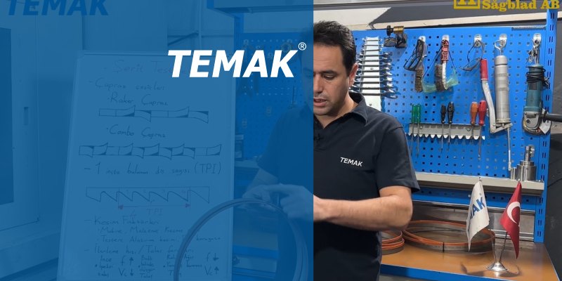
Bandsaw Blades: Correct Selection, Run-In and Cutting Methods

Bandsaw Blades: Correct Selection, Run-In and Cutting Methods

A fundamental building block of material cutting in machining, bandsaw blades deliver maximum life and high cut quality when used with the correct tooth form, suitable operating parameters and a proper run-in procedure.

Watch Temak Teknik’s informative video below covering bandsaw blade selection, tooth types, run-in steps and safe coiling methods:

Bandsaw Blade Material Structure and Types

The widely used bi-metal bandsaw blades combine a flexible spring steel backing with HSS (high-speed steel) tooth tips:

  • M42 Bandsaw Blades: Contain approximately 8% cobalt in the HSS teeth. With high heat and wear resistance, they are widely used for cutting general construction steels.
  • M51 Bandsaw Blades: Cobalt content is increased to over 10%. Suitable for cutting difficult-to-machine materials such as stainless, duplex, titanium and hardened steels.

Tooth Pattern and the TPI (Teeth per Inch) Concept

  • TPI (Teeth Per Inch): The number of teeth per 1 inch (25.4 mm).
  • Tooth Pitch Selection: For solid material, coarser teeth (lower TPI) are preferred as diameter increases to allow chip evacuation; for thin-walled tubes, profiles or soft materials (aluminium, plastic), finer tooth pitches are preferred.
  • Tooth Set Patterns: To allow chips to evacuate freely and to balance cutting forces, raker (right-left-straight) or combo (groups of varying pitch) tooth sets are used.

The Most Critical Step for Blade Life: Run-In

The tooth tips of a newly fitted bandsaw blade are extremely sharp. If cutting starts directly at high feed, micro-cracks form in the teeth and the blade quickly becomes dull.

  1. Idle Run-In: After fitting the blade and setting the tension, run it idle for 10 minutes at maximum speed with coolant on (to relieve stresses in the weld area).
  2. Half-Load Run-In: When cutting starts, reduce the blade speed and down-feed rate by at least half (50%) and cut for the first 10 minutes. Then gradually increase to normal cutting rates.

Analysing Cutting Conditions from Chip Form

The form of the chips produced during cutting shows whether you are using the correct speed and feed:

  • Thin, Powdery Chips: Feed rate too low or cutting speed too high. Increase feed or reduce speed.
  • Curled / Spiral / Comma-Shaped Chips: Ideal cutting conditions. Indicates the correct balance of speed and feed.
  • Thick, Heavy and Burnt (Black) Chips: Feed rate too high or cutting speed too low. Reduce feed or increase cutting speed.

Important Shop-Floor Recommendations and Safety

  • Interrupted Cuts: Never restart in a cut left unfinished due to tooth breakage or jamming. Work hardening of the material or remaining tooth fragments will immediately break the new blade as well. Shift the part slightly and start from scratch on a clean surface.
  • Coolant: The soluble oil emulsion concentration should be kept within at least the 4% – 6% range.
  • Safe Coiling: Always wear cut-resistant work gloves when coiling bandsaw blades; support the blade under your foot, twist it from the body and coil it safely into loops using a crossed figure-of-eight movement.